Skip to content Skip to side menu

Goodson Gazette

Automating the Valve Lapping Process

Creating a perfect, airtight seal by mating a valve to its seat can be a long, detailed process. Automating it with Goodson's powered valve lapping tools can make it more efficient, saving you time and money. Unlike a standard drill that spins continuously, a pneumatic tool like the Goodson Air Powered Valve Lapping Tool uses compressed air to mimic the manual "back-and-forth" oscillating motion at a much higher and more consistent frequency.

The Operational Process

Using a pneumatic lapper generally follows these professional steps:

  1. Preparation: The cylinder head and valves are thoroughly cleaned of carbon deposits. A small amount of abrasive lapping compound (grinding paste) is applied to the valve face.
  2. Setup: An appropriately sized suction cup is attached to the tool's head to match the valve diameter. The valve stem is lightly oiled to ensure smooth movement within the guide.
  3. Lapping: The tool is connected to shop air (typically around 90 PSI). As the tool oscillates the valve, the operator provides light pressure, occasionally lifting the tool slightly to redistribute the compound.
  4. Monitoring: The process continues until the gritty grinding sound transitions into a smooth, high-pitched hum.
  5. Verification: After cleaning away the paste, a successful "lap" is indicated by a uniform, dull gray ring around both the valve face and the seat.

Benefits Over Manual Lapping

  • Consistency: The tool maintains the same stroke length and frequency across all valves, which is difficult to achieve by hand as the operator tires.
  • Efficiency: It significantly reduces the time required for multi-valve heads (e.g., 16 or 24-valve engines), turning a weekend project into a quick task.
  • Precision: The oscillation prevents the formation of grooves or "trenches" that can occur if a valve is simply spun in one direction at high speed.

Key Equipment Options

Tool Type Best Use Case Features
Goodson Air Powered Tool Professional/Race Shops Operates on 90 PSI, highly durable
Pneumatic Valve Grinder Kits General/Automotive Repair Often includes multiple suction cup sizes and adjustable speeds

Read more →

Spring-Cleaning - A Great Time to Organize Your Shop

A solid spring-cleaning plan for a machine shop starts with restoring safety, improving workflow, and extending machine life.

Core Areas to Tackle First

These are the high-impact zones that usually accumulate the most risk and inefficiency.

  • Chip and debris removal – machines, floors, pits, coolant trays - Built-up chips trap moisture, hide leaks, and accelerate wear. Clearing them also exposes issues you might not otherwise see.
  •         Coolant systems – dump, clean, recharge – Old coolant grows bacteria, corrodes components, and affects part finish. Spring is a good time to reset concentrations and clean sumps
  •          Air handling – compressors, dryers, lines, filters – Drain tanks, replace filters, check for leaks, and clean intake screens. Air quality directly affects tool life and machine accuracy.
  •          Electrical panels and cable management – Blow out dust (with proper lockout/tagout),

Machine-Specific Deep Cleaning

A structured checklist helps prevent missed steps.

  •          Way covers and linear rails – remove chips, wipe down, re-lubricate.
  •          Spindles – check runout, clean tapers, inspect drawbar force if you have the tool.
  •          Hydraulic systems – inspect hoses, check fluid levels, clean filters.
  •          Coolant nozzles and manifolds – unclog and realign.
  •          Machine leveling – verify and adjust if needed after winter temperature swings.

Safety and Compliance Refresh

Spring is a natural time to reset safety standards.

  •         Fire extinguishers – check dates and pressure.
  •          PPE stations – restock and replace worn items.
  •          Chemical storage – reorganize, relabel, dispose of expired materials.
  •          Emergency stops and guards – test every machine.
  •          Floor markings – repaint walkways, forklift lanes, and hazard zones.

Shop Layout and Workflow Improvements

Once everything is clean, it’s the perfect moment to rethink flow.

  •          Reorganize high-traffic areas to reduce walking distance.
  •          Group tools by process (e.g., turning, milling, inspection).
  •          Add shadow boards or labeled drawers to reduce search time.
  •          Review material flow from receiving → machining → inspection → shipping.

Read more →

Replacing V-Twin Valve Springs or Seals Without Removing the Cylinder Head

Sounds like magic doesn’t it?

Let me assure you, it’s not magic. It’s simply one of the coolest tools we’ve seen in a long time. We call it the V-Twin On-the-Engine Valve Spring Compressor (Order No. CF-HDIF). You can use it to replace broken valve springs, install high performance springs, remove and replace valve guide seals all without completely disassembling the motorcycle.

Read more →

The Ins and Outs of Pressing Piston Pins and Bushings

This week we’re going to talk about removing and installing piston pins and bushings.

Old Hydraulic Shop PressIn order to prep your con rods for machining, you will need to have a few items. First, you’ll need a shop press. Goodson recommends you ask yourself a few questions when looking to add a shop press.

  1. What is your budget?
  2. What do you plan to do with the press?
    Usually when someone gets a press, they find all kinds of things to use it for. From pressing out pins and bushings to straightening pieces, etc.
  3. How strong of a ram do you need?
    For pressing piston pins and bushings, you’ll need a minimum of 5 tons of pressure, but you’ll probably want to go up to 20 to 30 tons if not higher, depending on what you plan to do with it.
  4. How much room do you have for a press?
    Presses are available in lots of sizes from bench-top units to large free-standing ones. Depending on what you plan to do with the press, you will also need room around the unit so keep that in mind when choosing a press.
  5. What’s your power source? Is it hydraulic or air over hydraulic? Both have their advantages and disadvantages.

For pressing piston pins and bushings, you’ll need a minimum of 5 tons of pressure, In our experience, most pins should break loose at 1800 to 2200 PSI. If you’re still running into resistance at this point, you have other problems. If all you’re going to do with the press is work on con rods, you can use a bench-top model but as we said before, you’ll probably find all kinds of uses for a press.  You also need be sure it is rigid and durable. Look for quality welded joints and heavy gauge metal.

When deciding which press to add to your shop, you will also want to check out the machine’s warranty. Remember, a shop press is as important an investment in your business as any of the other shop machines you use.

Now that you have the press, you’ll need some fixtures and tooling with which to work. Goodson offers several units for piston pin pressing and for pressing pin bushings, particularly tapered pin bushings. We’ll look at each one separately.

 Piston Pin Removal Fixture (PPE-7082) set-up

Piston Pin Removal & Installation Fixture (PPE-7082)

This fixture is composed of several parts that combine to take some of the guesswork out of removing and installing interference fit piston pins. It is designed to protect high dollar pistons from damage since the piston itself is NEVER under pressure. One of the key features is a series of support inserts that you use to keep the connecting rod aligned properly. Several standard sizes are available, plus one that is ready to be machined to your exact needs.  For a complete run down on how to use the Piston Pin Removal and Installation Fixture, check out the product instructions.

In addition to the standard instructions, Goodson Techxpert, Ed Koenig gives these key tips:

  1. Use the fixture with the press plates that came with your press
  2. Always select the proper insert. Be sure it fits the piston and pin properly
  3. Always use Press-Fit Lube (Goodson PFL-200) during the removal and installation process
  4. Verify alignment, verify alignment and verify alignment
  5. The piston must float during installation
  6. The rod must be centered on the pin for proper installation

One last warning that applies with all of these operations: If you run into excessive resistance, do NOT keep applying pressure. You can easily cause damage.

Universal Piston Pin Press-Out Tool (PPE-1)

Cross-Section of piston pin press set-up set-upA universal tool set to use with your shop press, this tool is made of high-quality steel and is sized to work with most applications. The set is designed for basic removal of pins without damage to the piston. Using the Piston Pin Press-Out Tool is pretty self-explanatory, but you can check out the product instructions for more details.

As with the Piston Pin Removal and Installation Tool, always be sure to use correctly-sized support fixtures, use press-fit lube and verify your alignment to avoid damage to the work piece.

Goodson Tapered Pin Bushing Press Kit (TB-KIT)

Universal Tapered Pin Bushing Press Kit (TB-KIT)

The Universal Tapered Pin Bushing Press Kit is designed to work on common light to medium duty diesel applications. It can be used to remove and install tapered pin bushings.

Why should a shop invest in the Universal Tapered Pin Bushing Press Kit?

  1. It’s the best tool for removal and installation of tapered connecting rod bushings up to 2″ in diameter.
  2. The tool is designed to prevent piston damage during use.
  3. With the number of bushing drivers included in the kit, it can accommodate many sizes of tapered rods.
  4. Specially sized bushing drivers can be made to order.
  5. You never have to make-do with different methods when installing or removing tapered bushings.

For more specific information, check out the product use instructions.

As always, if you have any additional questions about these or any Goodson products, contact the Goodson Techxperts by email or call 1-800-533-8010.

Read more →

Give Your Boss a Makeover

Give Your Boss a Makeover

Most stock cylinder heads come with press-in studs as standard. These are typically sufficient for everyday driving and moderate performance applications. However, for high-performance engines, especially those with high lift cams or high RPMs, upgrading to screw-in studs is often recommended. Screw-in studs provide a more secure and durable connection, reducing the risk of stud pull-out under extreme conditions.

Stud boss facers play a crucial role in the realm of cylinder heads and valvetrains.

What are Stud Boss Facers?

  • Imagine you're peeking under the hood of an engine. You spot those stout metal studs poking out from the cylinder head, holding the rocker arms in place. Those studs have a boss - the raised area around them.
  • Sometimes these bosses need a makeover. They might be too tall, uneven, corroded or flexed.

Why are they necessary?

  • Screw-in rocker studs: They are threaded and can be adjusted for precise rocker arm geometry, but they demand a well-prepped boss to sit on.
  • Stability and alignment: The stud boss needs to be flat and at the right height. If it's wonky, your rocker arms won't work harmoniously with the valves.
  • High lift cams and stout springs: When you are pushing the limits with aggressive cams and beefy springs, the stud boss needs to be solid, or it might crack under pressure. 

How to give the Stud Boss a makeover?

  • Remove the cylinder heads.
  • Use Goodson's Stud Boss Facer (SBF-5587) tool to cut most of the boss off to relieve the pressure. The stud will then come out without breaking the boss.
  • You will end up with a thin "post" that needs a gentle whack with a chisel to remove it.
  • Countersink the hole to help start the tap.
  • Repeat this process for all the studs.


    Read more →

    Handling Hazardous Materials

    Handling Hazardous Materials

    Over the years, technicians have generally taken the variety of chemicals and chemical byproducts in their workplace for granted. While it is easy to view efforts at controlling these substances as regulatory meddling, these materials can pose risks to workers’ health and safety. They may cause skin and eye irritation or more serious conditions like respiratory issues, neurological damage or cancer.

    Hazardous materials are defined in regulations as ignitable, reactive, corrosive or toxic. Their defining characteristics include the following:

    1. Ignitable materials have a flash point below 40 degrees F or ignite spontaneously or by friction.
    2. Corrosive materials have a pH below 2.5 or above 12.5 and corrode steel at a rate of .250 in. or more per year at a temperature of 128 degrees F.
    3. Reactive materials are unstable, change violently, form explosive mixtures or generate toxic fumes.
    4. Toxic materials are poison if ingested or inhaled or are carcinogenic.

    Information describing the contents, hazards, and first aid is included in Safety Data Sheets or SDSs. If you are uncertain of the products content or are considering using a new product, check the information contained in the SDSs. They are available on Goodson’s website under the Tech Support tab.

    While forms vary, the primary sections of an SDS contain the following:

    Section 1 - General Information

    Who makes the product and their address, emergency phone number, trade name and the product formula (unless proprietary).

    Section 2 - Hazardous Ingredients

    Chemical identification of components and exposure limit guidelines.

    Section 3 - Physical Data

    Appearance and odor under normal conditions, specific gravity, boiling point, vapor pressure, vapor density and evaporation rate.

    Section 4 - Fire and Explosion Data

    Indicates what kind of fire extinguishers to use, the flash point, special firefighting procedures and any special dangers.

    Section 5 - Reactivity Data

    What the chemicals react with and, if they do react, what might happen. It also tells what situations to avoid so there are no unexpected chemical reactions.

     Section 6 - Health Hazard Data

    How the chemical can enter the body through inhalation, eyes, or skin contact and what symptoms might exist. This section also gives emergency first aid procedures.

    Section 7 - Spill or Leak Procedure

    Includes what to do if there is a spill or leak, equipment and procedure for cleaning up the spill, method of disposal/special precautions.

    Section 8 - Special Protection

    Safety measures for adequate protection such as a respirator, gloves, ventilation, eye protection, or protective clothing for safe handling of different chemicals.

    Section 9 - Special Precautions Transport and Handling

    Special handling requirements in relation to temperature, open spark humidity and special containers.

    These regulations encourage business and industry to reduce worker and environmental exposure to hazardous materials. Remember, safe operations are attainable with proper risk management and precautions.


    Read more →

    Speeds & Feeds

    Finding the right combination of speeds and feeds is crucial for achieving longer tool life, faster machining speeds, and better surface finish. This handy table provides the information and formulas you need to calculate the best material cutting speeds and feed rates for milling, turning/boring, drilling, and reaming. Some practice is required to apply these formulas correctly. 

    Some practice is required to apply these formulas correctly. The following sample problems are typical of those encountered in an automotive machine shop.

    Read more →

    Measuring Clearance in Engine Bearings With Plastigage

    Plastigage is a simple and cost-effective method for measuring the clearance (separation) between fitted or hidden surfaces in engine bearings, Here's how it works.

    1. Prepare the surfaces:
      First, separate the surfaces between which you want to measure the clearance
      - Ensure that the surfaces are clean before using Plastigage.
    2. Apply Plastigage:
      - Cut a piece of Plastigage to fit across the bearing journal (the contact surface).
       - Place the Plastigage on top of the journal.
    3. Torque Down:
      - Install the bearing cap (or rod cap) and torque it down to the specified value and angle.
      - The Plastigage will be compressed between the bearing and the journal.
    4. Check Clearance:
      - Remove the bearing cap and compare the flattened Plastigage with the scale on the Plastigage packaging.
      - The width of the flattened Plastigage corresponds to the clearance.
      - Use the calibrated scale to determine the actual clearance. You can interpolate between scale marks for greater accuracy.
    5. Repeat for Other Bearings:
      - Repeat the process for other bearings in the engine.

    Advantage of Plastigage: 

    • Inexpensive compared to bore micrometers.
    • Useful for measuring clearances in split bearings or where feeler gauges cannot be inserted.

    Remember to follow the specific procedures for your engine and refer to the manufacturer's specifications.

    Read more →

    5 Tips for Replacing Valve Seals

    1. Use the right tools.

      Some people try to use pliers, screwdrivers or some other improvised tool to remove valve seals. This can lead to damaged seals, valve stems, valve guides or even yourself. You’re going to need at least two tools to remove valve seals properly: a spring compressor and a seal removal tool.

    2. Release spring pressure in a controlled manner.

      This is where a quality valve spring compressor is essential. You want to release spring pressure gradually to protect the valves, springs, guides and other valvetrain components from dropping into the cylinder or flying all over the shop. This will make it much easier for you to reach in and release the valve seal.

      Goodson VSP-323 Valve Seal Puller
      We recommend a valve seal remover that grips the seal without applying too much pressure which can crush the seal or mar the valve stem. The Goodson VSP-323 Valve Seal Puller has three fingers with tips that act like fingernails to slip under the bottom of the seal to pull it free. It is sized to work within the limits of the bucket bore.

    3. Clean the valve stem and guide before installing a new seal.

      Don’t skip this step or you may be replacing your valve seals sooner rather than later. When you clean the valve stem and valve guide before installing a new seal, you’re removing the dirt, oil, debris and general gunk that get in the way of a proper seal. Use a soft rag or shop towel to clean the stem and guide thoroughly before installing the new seal.

    4. Lubricating a valve spring before installation
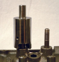
Lubricate the seal before installation.

      You might be tempted to install the new seal dry, but this can cause the seal to tear or crack during installation. It can also create heat and friction during operation. We recommend always using some engine oil or assembly lube to coat the new valve seal before sliding it onto the valve stem and guide.

    5. Align the new seal properly.

      Close up of mechanic installing a valve stem seal
      Pay attention to how the new seal sits on the valve stem. It should be firmly seated, but not too tight. Don’t use too much pressure when installing the seal either. This can cause the seal to be crooked, loose or damaged. Align the seal with the groove on the valve stem and use a seal installer to gently tap it into place.

    Read more →

    Measuring Combustion Chamber Volume

    The volume of a cylinder head's combustion chamber is an incredibly important spec. Too big, and you are leaving compression on the table. Too small, and you might hurt the engine. Measuring it isn't hard, but you need to follow the right steps in order to get an accurate result.

    Goodson teamed up with EngineLabs.com to create this tech article and video.

    Read the related article!

    Related Products:

    Read more →

    1 2 3 24 Next →