Pistons should be inspected and measured at several locations including the skirt, top, middle and bottom ring lands and the pin bore.
The skirt should always be measured exactly 90º from the pin bore. The actual height location may vary from manufacturer to manufacturer, but most specify a location the same height as the pin bore location.
After inspecting the ring lands, check each with a new ring. It is important to use new rings for the measuring procedure because wear will reduce the width of the old rings. A feeler gauge is placed between the ring and the top of the land. Under no circumstances should the ring-to-land clearance exceed .006” (0.15mm). Worn out ring lands do not let the rings seal in the explosive pressures of the burning air-fuel charge. It is not advisable to reuse pistons during a rebuild and rings should never be reused.
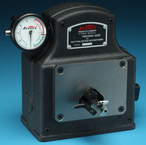
The pin bore must be gauged with the AG-300 Precision Gauge. Bores should be round and straight, showing no signs of taper or out-of-round. Those exceeding .0005” (.013mm) should be fitted with oversize pins. The following procedure is used to measure the piston:
- Select an appropriate sized micrometer and measure the piston skirt 90º from the pin hole location, as per manufacturer specifications. Record this measurement. Remember that the piston skirts are cam-ground (see image above).
- Measure the skirt just below the bottom ring groove and then measure the lowest part of the skirt. Record both measurements. Use them to determine the amount of taper found on the skirt. The bottom part of the skirt will always be larger than the top.
- Install a new piston ring backwards into the top ring groove. Insert the largest thickness feeler gauge that fits between the ring and groove. If the thickness exceeds .006” (0.15mm), replace the piston.
- Measure the pin bore for size and out-of-round, as per manufacturer’s specifications. Any deviation over .0005” (.002mm) is unacceptable and may require the installation of an oversize pin.
Piston Pins
Inspect your piston pins for damage. Complete failure (breakage) of the piston pin is a very rare occurrence in engines. Damage caused from incorrect fit or detonation, however, are commonplace. Improper installation of the pin can cause galling of the pin, rod and piston. If left uncorrected, the piston pin bore will quickly fail. Oversize pins can often be fitted to the piston and rod to salvage the assembly.
Detonation damage to the piston pin can also lead to early pin failure. Over-advanced ignition timing is the likely cause. Another common problem you’ll see is pin damage due to inadequate use of assembly lube.
Connecting Rods
Today’s connecting rods strain under 3,000+ HP in racing engines or as few as 50 to 300 HP in a passenger car. Regardless of the vehicle’s use, the connecting rod must be free of defects, straight and on-size. If the connecting rod is overlooked during an engine rebuild, the result is shortened engine life.
The tunnel or housing bore of the rod plays a significant role in engine operation. It must be round and parallel to the piston pin bore. Surface finish must be quite low in order to efficiently transfer heat away from the bearing inserts.
After many hours of operation the housing bore can become out-of-round. The majority of the out-of-round condition can be measured where the cap and rod mate (the parting edge). Measurements at the parting edge tend to be larger than when the rod is measured end-to-end. Out-of-round is what we call the condition when one measurement location is larger than another 90º away. A limited amount of out-of-round is acceptable.
Connecting Rod Measurement
The connecting rod must be measured for alignment. In addition, it must be measured at the rod journal bearing housing (tunnel) bore, the piston pin (tunnel) bore and the center-to-center distance. The bearing housing and pin bores are measured with a Sunnen AG-300 precision gauge or dial bore gauge for size and out-of-round. Center-to-center distance can be measured with a vernier caliper.
The center-to-center distance between the large and small ends of the connecting rod must be maintained within .005” (0.13mm); in most cars, less is better. Diesel engines often require a maximum variation of .002” (0.05mm). The large and small ends of the rod should be measured for out-of-round, taper and barrel, and should not exceed a variation of .0005” (0.002mm). Measurements are performed with the Sunnen AG-300 Precision Gauge or with a Dial Bore Gauge. A snap gauge or inside micrometer is NOT advised.
Here’s how to measure the connecting rod with the AG-300:
- Set your micrometer to the minimum or maximum housing bore diameter.
- Install the appropriate gauge points onto the gauge fingers (see chart). Adjust the AG-300 precision gauge indicator needle to zero and lock into place.
- Place the rod onto the measurement points near the parting edge (beam facing 12 o’clock or 6 o’clock position) so that the thrust surface of the rod lays flat against the face of the AG-300. Next, rotate the rod until you obtain a minimum reading (rod beam will be located at or around the 3 o’clock or 9 0’clock position on the indicator). Any deviation from the maximum bore means that the rod should be resized by honing or boring.
- Place a pair of the appropriate-diameter piston pins into the setting block and clamp into place. Adjust the AG-300 Precision Gauge (zero the indicator needle) and lock into place.
- Place the pin end of the connecting rod onto the measuring points and rotate until you obtain the maximum size. If the size exceeds the manufacturer’s specifications the rod will need to be reconditioned.
| AG-300 GAUGE POINT RANGE | ||
| RANGE | MINIMUM | MAXIMUM |
| Midget | .375” (9.53mm) | .750” (19.05mm) |
| Standard | .720” (18.29mm) | 1.530” (38.86mm) |
| Medium | 1.500” (38.10mm) | 2.250” (57.15mm) |
| Large | 1.940” (49.28mm) | 2.690” (68.33mm) |
| X-Large | 2.625” (66.68mm) | 3.375” (85.73mm) |
One last warning; the area from 2 o’clock to 8 o’clock and 3 o’clock to 9 o’clock positions will experience the most out-of-round condition.
The rod is considered acceptable if the parting edge location does not entirely clean up during the reconditioning process. This small area allows a small pool of oil to form and provides increased oil wedge during lubrication. To promote this same effect, some bearing manufacturers make a “Delta-wall” bearing where the edges of the insert are thinned. By thinning the edges you promote the formation of an oil pool.
Connecting rods stretch slightly at the parting line during extreme operating conditions. The housing bore pulls in toward the journal, while the center-to-center length increases. Over long periods of time, the housing bore is forced out-of-round to a point that it never returns to a round shape.
Rods having “gone to metal” (housing bore making physical contact with the crankshaft) must be inspected very closely during non-destructive testing (NDT). Metal build-up on the housing bore interior should be removed with a file before reconditioning. It is imperative that these rods be resized before returning them to service. Should cracks or fractures be found during NDT, replace the rod without hesitation.
The press-fit piston pin retention system is used on most engines. It is important to measure the pin bore for size. Press-fit pin bores are made slightly smaller (approx. 0.0008” to 0.0012” or 0.02 to 0.03mm) than the diameter of the pin. CAUTION: Always measure the pin bore before the pin is installed. Excessive material in the pin bore will cause the pin to seize half-way through during installation and cause the pin to become loose. Oversize pins are available for most applications to correct loose fitting or out-of-specification pins. In the majority of cases, press-fit pin bores do not require reconditioning. If a press-fit pin must be resized for an oversize piston, so too will the piston pin bore.
On rods fitted with free-floating pins, bronze bushings are used to support the pin. There are two methods used for their repair: Fit an oversize pin to the rod and piston; or remove and replace and fit a new pin bushing for the same (stock) size pin.
The housing the pin bores must be perpendicular to one another. Misalignment can cause rubbing or the piston skirts on the cylinders and cause edge-loading on the bearing by the crankshaft. Both problems will result in early engine failure. Measurement of the rod for twist, bend and center-to-center distances are made with sophisticated rod alignment machines.
Goodson thanks Sunnen Products Company for permission to use this information from Sunnen’s Complete Cylinder Head and Engine Building Handbook.