Skip to content Skip to side menu

Goodson Gazette

Give Your Boss a Makeover

Give Your Boss a Makeover

Most stock cylinder heads come with press-in studs as standard. These are typically sufficient for everyday driving and moderate performance applications. However, for high-performance engines, especially those with high lift cams or high RPMs, upgrading to screw-in studs is often recommended. Screw-in studs provide a more secure and durable connection, reducing the risk of stud pull-out under extreme conditions.

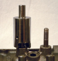
Stud boss facers play a crucial role in the realm of cylinder heads and valvetrains.

What are Stud Boss Facers?

  • Imagine you're peeking under the hood of an engine. You spot those stout metal studs poking out from the cylinder head, holding the rocker arms in place. Those studs have a boss - the raised area around them.
  • Sometimes these bosses need a makeover. They might be too tall, uneven, corroded or flexed.

Why are they necessary?

  • Screw-in rocker studs: They are threaded and can be adjusted for precise rocker arm geometry, but they demand a well-prepped boss to sit on.
  • Stability and alignment: The stud boss needs to be flat and at the right height. If it's wonky, your rocker arms won't work harmoniously with the valves.
  • High lift cams and stout springs: When you are pushing the limits with aggressive cams and beefy springs, the stud boss needs to be solid, or it might crack under pressure. 

How to give the Stud Boss a makeover?

  • Remove the cylinder heads.
  • Use Goodson's Stud Boss Facer (SBF-5587) tool to cut most of the boss off to relieve the pressure. The stud will then come out without breaking the boss.
  • You will end up with a thin "post" that needs a gentle whack with a chisel to remove it.
  • Countersink the hole to help start the tap.
  • Repeat this process for all the studs.


    Read more →

    Handling Hazardous Materials

    Handling Hazardous Materials

    Over the years, technicians have generally taken the variety of chemicals and chemical byproducts in their workplace for granted. While it is easy to view efforts at controlling these substances as regulatory meddling, these materials can pose risks to workers’ health and safety. They may cause skin and eye irritation or more serious conditions like respiratory issues, neurological damage or cancer.

    Hazardous materials are defined in regulations as ignitable, reactive, corrosive or toxic. Their defining characteristics include the following:

    1. Ignitable materials have a flash point below 40 degrees F or ignite spontaneously or by friction.
    2. Corrosive materials have a pH below 2.5 or above 12.5 and corrode steel at a rate of .250 in. or more per year at a temperature of 128 degrees F.
    3. Reactive materials are unstable, change violently, form explosive mixtures or generate toxic fumes.
    4. Toxic materials are poison if ingested or inhaled or are carcinogenic.

    Information describing the contents, hazards, and first aid is included in Safety Data Sheets or SDSs. If you are uncertain of the products content or are considering using a new product, check the information contained in the SDSs. They are available on Goodson’s website under the Tech Support tab.

    While forms vary, the primary sections of an SDS contain the following:

    Section 1 - General Information

    Who makes the product and their address, emergency phone number, trade name and the product formula (unless proprietary).

    Section 2 - Hazardous Ingredients

    Chemical identification of components and exposure limit guidelines.

    Section 3 - Physical Data

    Appearance and odor under normal conditions, specific gravity, boiling point, vapor pressure, vapor density and evaporation rate.

    Section 4 - Fire and Explosion Data

    Indicates what kind of fire extinguishers to use, the flash point, special firefighting procedures and any special dangers.

    Section 5 - Reactivity Data

    What the chemicals react with and, if they do react, what might happen. It also tells what situations to avoid so there are no unexpected chemical reactions.

     Section 6 - Health Hazard Data

    How the chemical can enter the body through inhalation, eyes, or skin contact and what symptoms might exist. This section also gives emergency first aid procedures.

    Section 7 - Spill or Leak Procedure

    Includes what to do if there is a spill or leak, equipment and procedure for cleaning up the spill, method of disposal/special precautions.

    Section 8 - Special Protection

    Safety measures for adequate protection such as a respirator, gloves, ventilation, eye protection, or protective clothing for safe handling of different chemicals.

    Section 9 - Special Precautions Transport and Handling

    Special handling requirements in relation to temperature, open spark humidity and special containers.

    These regulations encourage business and industry to reduce worker and environmental exposure to hazardous materials. Remember, safe operations are attainable with proper risk management and precautions.


    Read more →

    Speeds & Feeds

    Finding the right combination of speeds and feeds is crucial for achieving longer tool life, faster machining speeds, and better surface finish. This handy table provides the information and formulas you need to calculate the best material cutting speeds and feed rates for milling, turning/boring, drilling, and reaming. Some practice is required to apply these formulas correctly. 

    Some practice is required to apply these formulas correctly. The following sample problems are typical of those encountered in an automotive machine shop.

    Read more →

    Measuring Clearance in Engine Bearings With Plastigage

    Plastigage is a simple and cost-effective method for measuring the clearance (separation) between fitted or hidden surfaces in engine bearings, Here's how it works.

    1. Prepare the surfaces:
      First, separate the surfaces between which you want to measure the clearance
      - Ensure that the surfaces are clean before using Plastigage.
    2. Apply Plastigage:
      - Cut a piece of Plastigage to fit across the bearing journal (the contact surface).
       - Place the Plastigage on top of the journal.
    3. Torque Down:
      - Install the bearing cap (or rod cap) and torque it down to the specified value and angle.
      - The Plastigage will be compressed between the bearing and the journal.
    4. Check Clearance:
      - Remove the bearing cap and compare the flattened Plastigage with the scale on the Plastigage packaging.
      - The width of the flattened Plastigage corresponds to the clearance.
      - Use the calibrated scale to determine the actual clearance. You can interpolate between scale marks for greater accuracy.
    5. Repeat for Other Bearings:
      - Repeat the process for other bearings in the engine.

    Advantage of Plastigage: 

    • Inexpensive compared to bore micrometers.
    • Useful for measuring clearances in split bearings or where feeler gauges cannot be inserted.

    Remember to follow the specific procedures for your engine and refer to the manufacturer's specifications.

    Read more →

    5 Tips for Replacing Valve Seals

    1. Use the right tools.

      Some people try to use pliers, screwdrivers or some other improvised tool to remove valve seals. This can lead to damaged seals, valve stems, valve guides or even yourself. You’re going to need at least two tools to remove valve seals properly: a spring compressor and a seal removal tool.

    2. Release spring pressure in a controlled manner.

      This is where a quality valve spring compressor is essential. You want to release spring pressure gradually to protect the valves, springs, guides and other valvetrain components from dropping into the cylinder or flying all over the shop. This will make it much easier for you to reach in and release the valve seal.

      Goodson VSP-323 Valve Seal Puller
      We recommend a valve seal remover that grips the seal without applying too much pressure which can crush the seal or mar the valve stem. The Goodson VSP-323 Valve Seal Puller has three fingers with tips that act like fingernails to slip under the bottom of the seal to pull it free. It is sized to work within the limits of the bucket bore.

    3. Clean the valve stem and guide before installing a new seal.

      Don’t skip this step or you may be replacing your valve seals sooner rather than later. When you clean the valve stem and valve guide before installing a new seal, you’re removing the dirt, oil, debris and general gunk that get in the way of a proper seal. Use a soft rag or shop towel to clean the stem and guide thoroughly before installing the new seal.

    4. Lubricating a valve spring before installationLubricate the seal before installation.

      You might be tempted to install the new seal dry, but this can cause the seal to tear or crack during installation. It can also create heat and friction during operation. We recommend always using some engine oil or assembly lube to coat the new valve seal before sliding it onto the valve stem and guide.

    5. Align the new seal properly.

      Close up of mechanic installing a valve stem seal
      Pay attention to how the new seal sits on the valve stem. It should be firmly seated, but not too tight. Don’t use too much pressure when installing the seal either. This can cause the seal to be crooked, loose or damaged. Align the seal with the groove on the valve stem and use a seal installer to gently tap it into place.

    Read more →

    Measuring Combustion Chamber Volume

    The volume of a cylinder head's combustion chamber is an incredibly important spec. Too big, and you are leaving compression on the table. Too small, and you might hurt the engine. Measuring it isn't hard, but you need to follow the right steps in order to get an accurate result.

    Goodson teamed up with EngineLabs.com to create this tech article and video.

    Read the related article!

    Related Products:

    Read more →

    Intake Power Mods with David Vizard

    Our good friend David Vizard is back with another episode of Tech Lab Tuesday. In this episode, David moves on to part 9 of the St. Jude's Charity Mission Impossible 318 Mopar Build. Here he shows how to do just a metal removal job to increase the intake ports power potential by about 25%.

    Related Products

    Read more →

    Reconditioning High Silicon Aluminum Alloy Engine Blocks

    One of the most significant features of aluminum die-cast engine blocks is that they don't require steel or cast iron liners in the cylinder bores. Particles of pure silicon, averaging about .001" in diameter are dispersed throughout the engine block. As silicon is very hard, there will be very little wear in the cylinder bores. In fact, as far as pistons and rings are concerned, the cylinder wall IS silicon; the aluminum's function is simply to hold the silicon particles.

    Reconditioning Hints

    If cylinder bores in these blocks become excessively worn or scored, they can be honed to accept oversize pistons. Unfortunately, the sizing and finishing processes you would normally use leave cylinder wall of silicon and aluminum. The silicon particles no longer protrude from the aluminum.

    To achieve the proper surface for compatibility with the rings and pistons you will need to prepare the cylinder bores so the silicon particles protrude. This allows the pistons and rings to only contact silicon. A special conditioning operation is required to remove the aluminum from between the silicon particles.

    Read more →

    Trade Show Season 2023

    Mark your Calendar

    Mark your calendars now for the upcoming Automotive Trade Shows, Conferences and Conventions!

    PERA logoPerformance Engine Rebuilders Association 2023 Convention

    When: September 20-22, 2023
    Where: Houston, TX 

    Get More information 

    AERA Tech & Skills Regional Conferences Logo


    AERA Tech & Skills Conference

    When: October 6, 2023
    Where: Rottler Mfg., Kent WA

    Get More Information Now!

    ATRA Powertrain Expo Logo

    ATRA Powertrain Expo 2023

    When: October 25 - 29, 2023
    Where: Nashville, TN

    Get More Information Now!

    SEMA Show logo

    SEMA Show

    When: October 31 - November 3, 2023
    Where: Las Vegas, NV

    Get More Information Now!

    Performance Racing Industry Show

     Performance Racing Industry Show

    When: December 7 - 9, 2023
    Where: Indianapolis, IN

    Get More Information Now!

    Goodson will be attending the PERA Convention, AERA Tech & Skills Conference and the Performance Racing Industry Show. Come see us there!

    Read more →

    Tech Lab Tuesday Presents Low-Lift Flow

    Another great video from our friends at Jim's Auto Machine Shop in Colorado.

    This one is a treat for the diesel guys! Our customer came to us in need of help for their 550HP 7.3L Powerstroke... but we've already seen these heads once before.

    Products Used in this Video:

    Read more →

    1 2 3 24 Next →